Solar system commissioning is the systematic process of verifying, testing, and certifying that your newly installed solar energy system meets all technical specifications, safety standards, and performance requirements before it begins regular operation. It is the critical bridge between physical installation and the first kilowatt-hour of generation credited to your account.
Many solar owners treat commissioning as a formality — a few signatures before the inverter is switched on. In practice, it is a multi-day technical process that determines whether your system will perform as designed for the next 25 years or deliver silent underperformance that compounds into significant financial loss. Understanding what should happen during commissioning helps you verify that your EPC contractor is doing it properly.
In Gujarat, commissioning also encompasses grid approval from GUVNL and bidirectional net meter installation — a process with its own documentation requirements and timelines.
What Happens During Solar Commissioning?
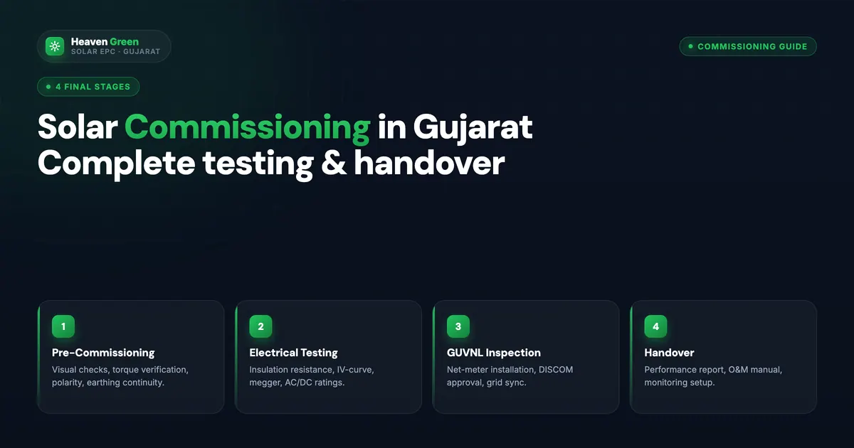
Commissioning for residential systems typically takes 3–7 days, with commercial installations requiring longer depending on system complexity and grid approval timelines. The process unfolds in five distinct phases:
- Pre-commissioning checks and visual inspection
- Electrical testing and verification
- Inverter configuration and anti-islanding testing
- Grid connectivity approval and net metering installation
- Performance verification and final handover
Phase 1: Pre-Commissioning Checks
Before any electrical testing begins, a thorough visual inspection establishes whether the physical installation meets design specifications and quality standards.
Module and Structural Inspection
- Panel mounting security: Every panel frame must be correctly fastened to the mounting structure with the specified hardware. Loose panels pose wind-uplift risks and create micro-vibration that can damage junction boxes over time
- Structural integrity: Mounting rails, clamps, and fasteners are inspected for correct installation — correct torque values, proper anti-corrosion coating, and secure anchorage to the rooftop structure
- Panel alignment: Panels should be uniformly aligned with no significant gaps or misalignment that could affect cable routing or future cleaning
- Junction box inspection: All panel junction boxes should be sealed and undamaged
Cable Routing Verification
- DC cables are correctly routed in UV-protected conduit or cable trays where exposed to direct sunlight
- Cables are secured at appropriate intervals with no sharp bends that could damage insulation
- Cable labels are applied at both ends for identification during future maintenance
- No cables are lying directly on hot metal rooftop surfaces without protection
- Positive and negative strings are physically separated where possible to reduce arc fault risk
Earthing and Lightning Protection
- Earthing conductors are connected from panel frames to the main earthing system
- Earth pit resistance is measured and documented — should comply with IS 3043
- Lightning protection system (if installed) is correctly bonded to the main earth
- All metallic enclosures — inverter cabinet, combiner box, disconnect switches — are earthed
Documentation Review
Before testing begins, the commissioning engineer should verify that all installed equipment matches the approved design:
- Panel model and quantity versus design drawings
- Inverter model and rating
- Cable specifications versus design calculations
- Protection device ratings versus design
Phase 2: Electrical Testing
Electrical testing confirms that the installed system is safe, correctly configured, and capable of producing the designed output.
String Voltage and Current Measurements
Each string is measured for open-circuit voltage (Voc) and short-circuit current (Isc) before connecting to the inverter or combiner box. Values should be within 5% of the design specifications calculated from the panel datasheet and ambient temperature at the time of testing.
Significant deviations indicate:
- Incorrect string configuration (too many or too few panels in series)
- A faulty or mismatched panel within the string
- A broken bypass diode in one or more panel junction boxes
- A polarity reversal in the string wiring
All deviations must be investigated and corrected before proceeding.
Insulation Resistance Testing
Insulation resistance testing uses a 500V or 1000V DC megohmmeter applied between each conductor and earth. Acceptable insulation resistance must exceed 1 megohm per IEC 62446 requirements.
Gujarat’s humid climate makes insulation testing particularly important. High humidity during the monsoon season and salt-laden air in coastal areas near Surat and Hazira accelerate insulation degradation in substandard cable materials. A newly installed system failing the insulation test has a defect that will worsen over time.
Low insulation resistance indicates:
- Damaged cable insulation from installation activity
- Moisture infiltration at connector or junction box
- Faulty panel junction box
Earth Continuity Testing
Earth continuity resistance between any metallic component of the array (panel frames, mounting structure) and the main earthing terminal should not exceed 1 ohm. High resistance indicates a broken continuity bond that renders the earthing system ineffective during a fault.
Polarity Verification
Every string polarity is confirmed before connection to the inverter. DC polarity reversal — connecting positive to negative — can damage the inverter’s input protection circuitry. Polarity verification should be documented string by string in the commissioning record.
Protection Device Verification
All DC and AC protection devices — string fuses, DC circuit breakers, surge protection devices, AC isolators — are verified for correct rating, correct installation, and operational function.
Phase 3: Inverter Configuration and Testing
Grid Parameter Configuration
The inverter must be configured with parameters matching Gujarat’s grid specifications:
- Voltage: 230V single-phase or 400V three-phase (as applicable)
- Frequency: 50 Hz
- Voltage tolerance range: ±10% of nominal
- Frequency tolerance range: 47.5–51.5 Hz (per CEIG and DISCOM requirements)
- Reconnection delay after grid disturbance: As specified by the relevant DISCOM
Inverters used in Gujarat should be tested and approved for Indian grid conditions. Using inverters configured for European or other grid parameters creates compliance issues during DISCOM inspection.
Anti-Islanding Protection Testing
Anti-islanding protection prevents the inverter from continuing to supply power to the local circuit during a grid outage — a critical safety requirement protecting utility lineworkers who may be working on what they believe is a de-energised section of grid.
Anti-islanding protection must cause the inverter to shut down within 2 seconds of grid failure. This function is tested during commissioning by simulating a grid outage and timing the inverter shutdown response. Failure to shut down within the required time is a DISCOM compliance failure and a safety hazard.
Power Quality Measurements
Commissioning includes measurement of:
- Total harmonic distortion (THD): Must meet grid code requirements — typically below 5% total
- Power factor: Should be close to unity (above 0.95) at normal operating conditions
- DC injection: The amount of DC current injected into the AC grid must not exceed the limits specified by the relevant grid code
Efficiency Testing
Inverter efficiency is verified by comparing DC input power to AC output power at a range of load conditions. Quality inverters achieve 97–98% efficiency at optimal load; significantly lower efficiency indicates a configuration or equipment issue.
Monitoring System Setup
The inverter monitoring system — whether the manufacturer’s app, a third-party monitoring platform, or a data logger — is configured and tested during commissioning:
- Connection to inverter data port verified
- Data logging confirmed with accurate timestamp
- Remote access configured and tested
- Performance alerts set up (generation below threshold, error codes)
Phase 4: Grid Connectivity and GUVNL Approval
The GUVNL Net Metering Process
Grid-connected solar systems in Gujarat require formal approval from the relevant Distribution Company (DISCOM) before the bidirectional net metering meter can be installed and the system legally energised. The process involves:
- Application submission: Technical drawings, equipment specifications, and completed application forms submitted to the relevant DISCOM (DGVCL for Surat, UGVCL for Ahmedabad, etc.)
- Technical review: The DISCOM reviews the application for compliance with grid connection requirements
- DISCOM inspection: A DISCOM engineer visits the site to verify installation compliance
- Meter installation: The existing unidirectional meter is replaced with a bidirectional net metering meter
- Grid energisation: The DISCOM authorises system energisation and commences net metering billing
Typical approval timelines:
- Major cities (Surat, Ahmedabad): 7–15 working days
- Smaller cities and towns: 15–30 days
- Rural areas with agricultural connections: up to 45 days in some cases
Experienced EPC companies with established DISCOM relationships typically achieve approvals at the lower end of these ranges. Applications with documentation errors or incomplete technical drawings face significant delays.
Documentation Required for DISCOM Application
- Completed DISCOM net metering application form
- Copy of existing electricity bill showing consumer number and sanctioned load
- Technical drawing — single-line diagram of the solar installation
- Equipment specifications — panel and inverter model, ratings, and certifications
- Site layout drawing showing panel placement
- Structural stability certificate (for rooftop installations)
- Copy of property ownership or lease documents
- Passport-size photograph and identity proof of consumer
Phase 5: Performance Verification
Performance Ratio Calculation
The performance ratio (PR) is the key metric for assessing overall system quality. It compares actual energy output to the theoretical maximum output the system could produce if operating at STC (Standard Test Conditions) efficiency.
A properly commissioned and installed system in Gujarat should achieve a PR of 75–85% depending on system age, panel quality, inverter efficiency, and local climate factors. New systems at commissioning should achieve the upper end of this range.
PR below 70% on a new system indicates:
- Equipment underperformance versus specifications
- Significant shading losses not identified during design
- Installation quality issues (incorrect string configuration, high-resistance connections)
- Monitoring system inaccuracy
Generation Capacity Testing
During peak solar hours — typically 11 AM to 2 PM on a clear day — the system’s AC output is measured and compared to the design output corrected for actual irradiance conditions at the time of testing.
If actual irradiance during testing is 900 W/m² versus STC irradiance of 1,000 W/m², the expected output is proportionally reduced by 10%. The commissioning engineer uses a calibrated irradiance sensor to make this correction.
Load Testing
For systems with backup capability or hybrid configurations, load testing verifies that the system correctly powers the intended loads during both grid-connected and off-grid modes.
Monitoring System Accuracy
The generation data displayed on the monitoring system is cross-checked against direct measurements from the inverter’s energy counter. Significant discrepancies indicate a data logging configuration error.
Common Commissioning Challenges in Gujarat
Grid Approval Delays
The most common cause of extended commissioning timelines is DISCOM approval processing. Submitting a complete, correctly formatted application at the earliest possible stage — ideally during the physical installation phase — minimises this delay.
Weather-Related Testing Interruptions
Cloud cover or monsoon weather during the commissioning window can prevent accurate performance verification. Commissioning engineers schedule electrical safety testing regardless of weather but may need to return for performance verification during clear conditions.
Documentation Gaps
Missing structural certificates, outdated equipment specifications, or incomplete DISCOM applications are the most common causes of DISCOM rejection and resubmission delays. Thorough documentation preparation before physical installation begins prevents this.
Technical Faults Requiring Correction
Commissioning testing occasionally reveals faults that must be corrected before system energisation — panel junction box failures, faulty MC4 connectors, earthing continuity breaks. These are the expected function of commissioning: finding problems before they become long-term performance issues.
Post-Commissioning Timeline
Following successful commissioning and grid energisation:
| Period | Recommended Action |
|---|---|
| First 30 days | Close daily monitoring of generation data — establish expected daily generation baseline |
| Month 1–3 | First professional maintenance visit — verify all connections remain tight, clean panels, check for error codes |
| Every 2–4 weeks | Panel cleaning (more frequently during dry summer months in Gujarat) |
| Annually | Professional inspection — electrical testing, thermal imaging, inverter check, earthing verification |
| Year 12–15 | Inverter replacement planning — inverters typically have 10–15 year useful lives |
Final Handover Documentation
A properly executed commissioning produces a complete documentation package:
- Commissioning report: Test results for all electrical measurements, performance verification, and anti-islanding test
- As-built drawings: Final electrical and layout drawings reflecting any changes from the design during installation
- Equipment documentation: Panel and inverter warranties, data sheets, operation manuals
- DISCOM approval documentation: Net meter installation certificate and account update confirmation
- Earthing test report: Earth pit resistance measurements
- Insulation test report: Results for each string and conductor
- Owner training record: Confirmation that the owner has been shown how to read the monitoring system, check for error codes, and perform basic visual inspections
Heaven Green Energy’s commissioning teams operate across Gujarat — Surat, Ahmedabad, Junagadh, and surrounding districts. Every installation we complete goes through our full commissioning checklist, and the documentation package is handed over to the customer before our team leaves site. For commissioning services or to discuss a new installation, contact us at +91 63904 05060 or email support@heavengreenenergy.com.